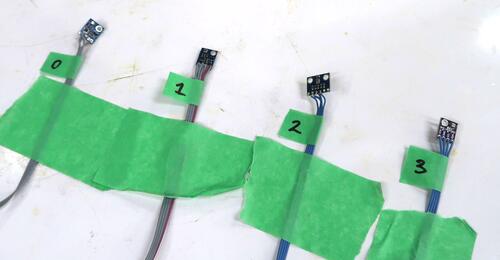
 There are a lot of sensors and A/D converters that can be connected to the I2C port on the
raspberry pi.
You can download the python script I was using in this video: tgraph.py
 There are a lot of sensors and A/D converters that can be connected to the I2C port on the
raspberry pi.
Multiple devices can be hooked up to the same port in parallel, but they need to each have a unique address. Each manufacturer chooses an arbitrary address for their chip, so you have to make sure you don't have two with the same address on the same I2C bus. But if you want to have multiple of the same type of chip on the same bus, that can present a problem.
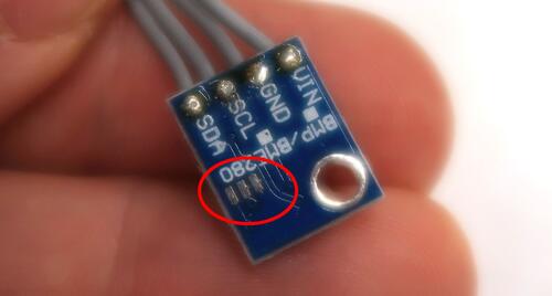 The BME280 or BMP280 sensors I like to use are on address 0x76, but the chip can also be set to address 0x77
by scratching out a trace and connecting between two pads on the sensor boards, so two BME280 sensors can
be on the same bus.
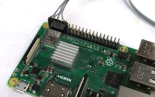 Conveniently, I2C port 1 (the easier to use I2Cport on the Pi) has the clock and data lines right next to each
other on the 40 pin header, and a 3.3 volt pin and a ground pin next to those.
So I usually just use a five pin connector and solder wires to that and plug that straight into the corner of the 40 pin connector.
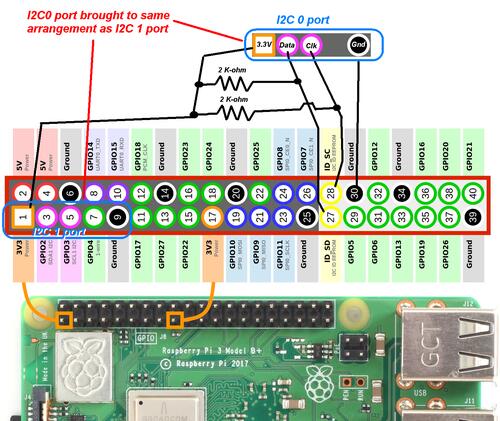 I2C port 0 isn't as conveniently arranged. Also, pull-up resistors need to be added between 3.3 volts
and the clock and data pins to use that port.
In addition, the following line needs be added to the file /boot/config.txt
dtparam=i2c_vc=on
Also, I2C must be enabled using raspi-config, and the camera module must not be enabled.
To check if the peripherals are properly connected, I run
sudo i2cdetect -y 1
To list the devices on I2C 1 (the normal port) and
sudo i2cdetect -y 0
To check the second I2C port.
You can Aso download the python script I was using: tgraph.py
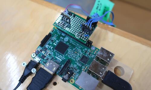 I built a little "pi hat" that brings the I2C 1 (pins 0,3,5,9) out to two headers, so two separate
connectors can be plugged in, and I2C 0 (pins 27 and 28, plus power and ground) to two more headers
with te same pin arrangement as I2C 1. That board also has the 2k-ohm pull-up resistors on it.
That way I can plug my devices into whichever port I want to.
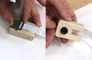 M12 lens mount for Pi camera module (video, 2020)
 My imgcomp program Motion triggered time-lapses. (2015-2021)