A while back, one of my readers told me about the Ontario Steam Heritage museum, a private museum located in Puslinch township in Southern Ontario.
The museum doesn't have a website, nor does it have regular opening hours, but it is open by appointment for private tours, clubs, and schools. I was given the phone number of the owner, Wayne Fischer.
 I was already planning on taking
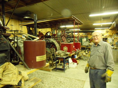
a trip to Waterloo, so I gave Wayne a call and we arranged for a viewing. Here's Wayne Fischer
showing me around. Wayne is very enthusiastic about steam engines and their history.
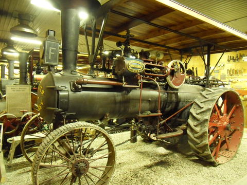
The main focus of the museum are steam traction engines such as the ones in this picture. One might be inclined to call one of these a steam tractor, but that is actually not the proper name for them.
 These steam traction engines, in their day, were quite expensive and a big deal. They weren't
the sort of thing most individual farmers could afford, so the bigger name seems appropriate.
Once smaller gasoline and diesel powered tractors became available, they weren't as big a deal
anymore, and so the more casual term "tractor" came into use.
Steam traction engines were originally developed in England in the 1860s. Manufacturing of traction engines in North America started in the 1880s. From the period from 1880 to the late 1920s, there were 86 manufacturers of traction engines in North America, with J.I. CASE manufacturing over half of them. Production peaked in 1911. At that time, the CASE company was manufacturing over one an hour, without using an assembly line. Sawyer-Massey, the manufacturers of the engine at left, was building three per day.
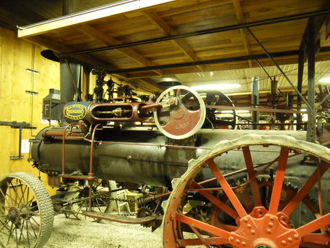 Wayne gave this particular traction engine as a wedding gift to his wife. This engine is a
1915 20 horsepower Sawyer-Massey manufactured in Hamilton, Ontario.
It has rubber threads from tractor tires attached to the steel wheels. The rubber threads are not an authentic modification, but it allows the engine to be driven on paved roads without damaging them. These engines get taken to parades and shows from time to time.
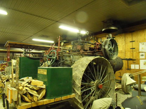 Most of these engines have cast iron "grouters" attached to the wheels, which dig into
soft soil for traction. But the grouters would damage paved roads.
This one is a 1912 85 horsepower double cylinder Nicolson Shepherd traction engine, manufactured in Battle Creek, Michigan. This particular engine broke virgin soil in 1912 in Daulthene Manitoba. The large flat fields of the west were well suited for ploughing by traction engine. It was the traction engine that opened the west for agriculture, whereas the east was first ploughed by oxen.
Traction engines were mostly bought by farmers, but also by road building contractors, machinery movers, and municipalities and counties for road work. The traction engines used for roadwork had much flatter grouters so as not to damage roads.
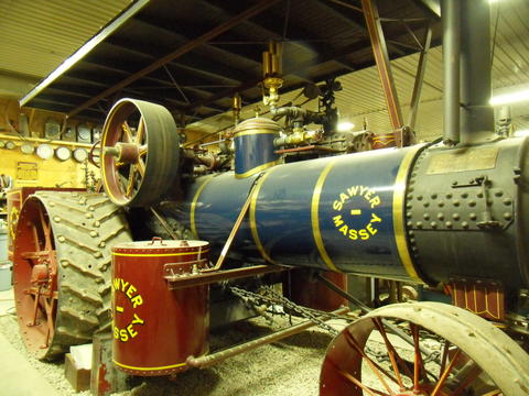 Welding hadn't been invented when most of these were built, so everything had to be made
out of riveted plate steel or from cast iron. No wonder they used so much cast iron back then!
Unfortunately, boilers rust out with time. Most of these engines have their boilers replaced at some point as the boiler walls became too thin. Each of these engines has a certified boiler, inspected annually by TSSA which administers the Boiler and Pressure Vessel Act for the province of Ontario. It only makes sense - you wouldn't want one of these exploding in the middle of a parade!
This one is a 1919 68 horsepower Sawyer-Massey that was originally purchased by the Department of Highways of the Province of Ontario. It still has its original brass government registration plate on the boiler near the front. It's reported to be one of the finest examples of traction engines in north America for condition and the quality of its restoration.
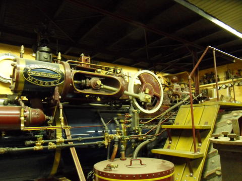 A close up of the same engine from the other side.
The wooden steps lead up to the service platform.
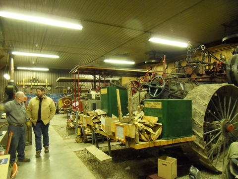 The Museum is mostly about the steam engines and their restoration.
One of the things they like to show is the mechanical technology and where today's technology
evolved from.
For me this makes the museum all the more interesting to figure things out.
These old engines and such are fascinating to look at.
Unlike modern engines, all the gears and links are exposed, so you can figure out how
most of it works just by following where the shafts and gears go.
In this photo, Wayne is next to Richard Mosher, chief engineer of the museum.
 The museum is a teaching museum and runs courses to allow individuals to
write the exam and serve their apprenticeship time to receive their operating certification
for steam engines.
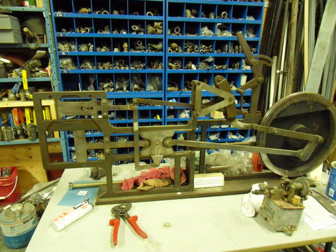
This is an "educator" which demonstrates the operation of the valve and the pistons in relation to each other. This educator was originally assembled by the grand trunk railway (later Canadian National) around 1902. It was used at the Stratford railway shop until 1958.
Steam engines typically have a bit of timing advance in the valves (that is, the valves move slightly ahead of 90 degrees with respect to the cylinder motion). This allows time to build up pressure before the working stroke begins. Also, unless running at full throttle, the inlet valve is closed long before the working stroke is finished to economize steam.
I always wondered how that works in connection with the reversing gear, because what is ahead in forward is behind in reverse. But there's an extra linkage to the piston slider to add the timing advance.
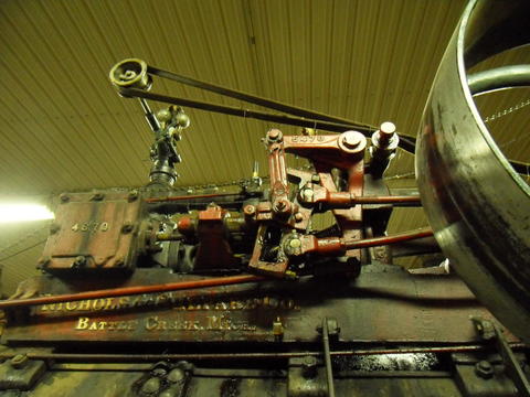 Another approach to this timing issue is to have a crank activate either side of
the reversing gear, as in this example. This particular type of mechanism is called the
Stephenson valve linkage. It was the first valve linkage that allowed you to
reverse the engine as well as economize the steam by only leaving the inlet
open for part of the power stroke, with the expansion of the steam finishing the stroke.
These engines look unsophisticated, but there's so much ingenuity to them. The people who designed these engines were just as smart as people today, but instead of designing yet another smartphone, they put their intellects to work on things mechanical.
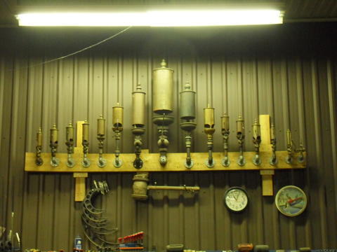 Steam whistles of various types. These were used for signalling. The larger ones
came from factories. Before everything was powered by electric motors, most factories were
powered by steam engines, so a steam whistle was easy enough to add. They were blown
at regular intervals to tell people what time it was.
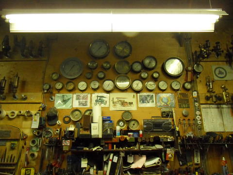
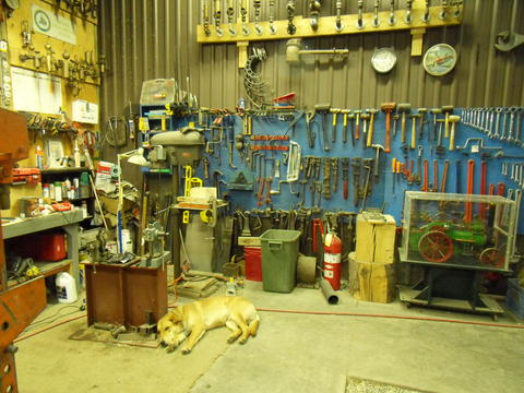 Lots of tools, some of which are quite unfamiliar looking, most of them old. Much like modern cars,
steam engines have specialized tools that are used for various jobs. You can enlarge the picture
by clicking on it.
If everybody drove steam traction engines instead of cars, I'm sure this is what every service station would look like!
Inside the Plexiglas case is a 1:12 scale fully working model of a British steam traction engine.
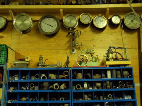 There are various scale models of steam engines everywhere. Some of these were laboriously made by
hand by retired machinists, and then at some point donated to the museum.
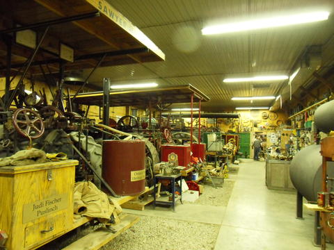 The floor is mostly cement, with gravel in each bay for the steam engines. There are even
smoke jacks to take the smoke through the roof so that the engines can be fired up
inside the building.
Wayne says this is probably the only building in north America where traction engines
can conveniently be run in the winter time. Otherwise, one would have to drain all the water
out of the engine when not in use, to prevent it from freezing.
Without the smoke jacks going through the roof, it wouldn't be possible to drive the engines in and out of the building under their own power.
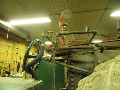 Here's an incredibly clever aspect to these old steam engines. It's called a "steam injector".
Basically, it's a sort of steam powered jet pump that is used to replenish the water
in the boiler while under pressure.
It's the little thing that looks like more plumbing to the right of the hose
near the middle of this photo.
Basically it uses the steam pressure from the boiler to push water into the boiler from the external water tank. The catch is, the water has to be pushed into the pressurized boiler, which is at the same pressure as the steam coming out of it, even without accounting for any friction losses. You'd think that sort of thing wouldn't be possible, but it works. You can read the Wikipedia article about steam injectors
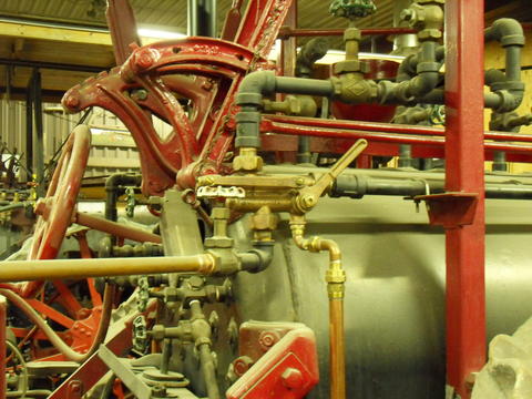 Here's another steam injector. Each engine has two steam injectors. You
need to have an alternate way of replenishing the water in the boiler
if one of them should fail. You don't ever want to run out of water in a steam boiler!
You can read more about it here:
www.the-nerds.org/Steam-101.html
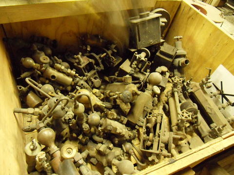 This is a box full of "hydrostatic displacement lubricators". There's a need to inject
steam cylinder lubricant into the steam flowing into the cylinder.
Steam cylinder lubricant is an oil mixture with about 10% tallow. The tallow allows
the oil to be emulsified and carried into the cylinder by the steam.
But the lubricant needs to be slowly injected at pressure. The displacement lubricators work by having a condensing chamber in them. As steam condenses, it turns into water and slowly runs down into the chamber full of lubricant. Water is heavier than oil so it displaces the oil (at pressure) which is then injected into the steam going towards the cylinder. This page (www.the-nerds.org/Steam-101.html) also explains more about that.
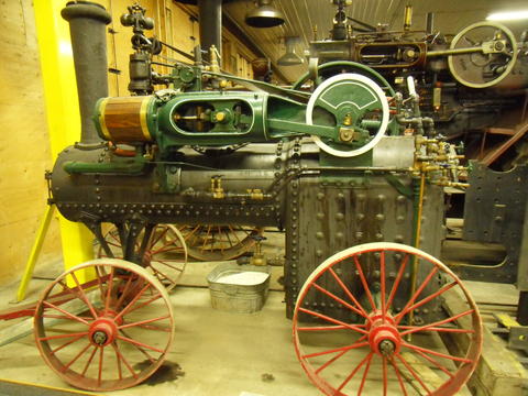 This one's a smaller "portable" steam engine, a precursor to the traction engines.
This type of engine was pulled by horses and used to power stationary loads such as threshing machines.
This engine has no power train to power the wheels off the engines. Whereas "traction" engines have
a gear train to power the wheels.
They started making this style of engine in the 1840s in England and 1850s in North America. They were built up until the 1920's, and were purchased by farmers who couldn't afford traction engines.
This one is a 1906 6 CASE portable. But it has a new boiler on it installed in 2008. It's an all welded boiler, can take 175 PSI pressure. The rivets were only added for looks.
As the threshing machines got larger, bigger engines were needed. The bigger engines were harder for horses to pull. So the logical next step was to add some gearing between the engine and the wheels so that it could move under its own power. Key inventions to making that practical were the differential gear, the clutch, and the steering gear.
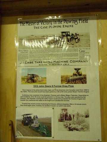 Of course, once you have a big heavy and powerful engine that can drive itself, the logical
next thing is to use it to pull a plough across the field.
This was the other main application of these traction engines. A 65 to 85 horsepower engine with an 8 furrow plough could plough 25 to 35 acres in day, compared to about one acre a day by horse.
Steam engines have some advantages over internal combustion engines in that they have full torque all the way down to zero RPM. You can start and stop the engine with the plough in the furrows without shifting gears or even using the clutch.
Wayne says that for an internal combustion engine to do the same effective work as a steam engine, it needs about 2.2 times more horsepower. It's because of the torque curve. An internal combustion engine needs some power headroom to avoid stalling as it will lose torque when it loses speed. Whereas a steam engine will only increase in torque as it slows down.
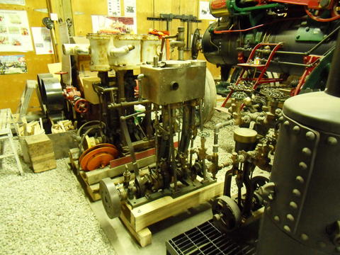 They have all kinds of engines. These are smaller ship's engines.
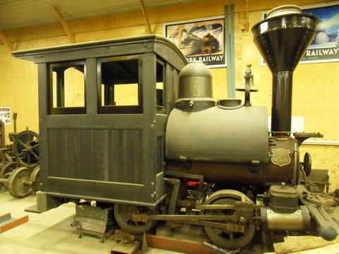 A locomotive that is being restored. The cabin is all new, but built to the original drawings.
This is a 1904 H.K. Porter locomotive. One of four shipped to consolidated gold mining north of Dawson city in the Yukon. It's called a "tank locomotive", with the water tank over the boiler. This type of engine was used to haul things back and forth over short distances. It was operated without a tender. A small supply of coal was kept in the cab.
This one is a 1909 Vulcan locomotive (without the cab), made in Pennsylvania. It was brought to Canada to help build the Trent canal.
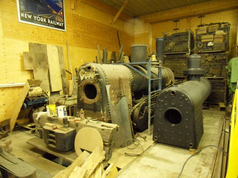
To the right of it is a new boiler for this engine. When there's just a boiler and fire box, steam locomotives and traction engines don't look that different.
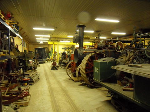 The lines you see on the floor are actually train tracks. There are three rails, to accommodate
standard gauge and 36" narrow gauge. The leftmost of the rails is obscured by palettes on the floor.
The plan is to eventually have a small train track around the property
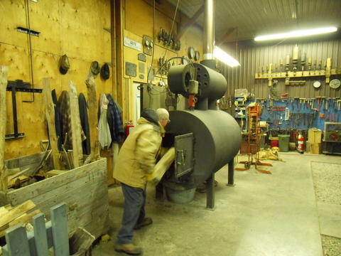 There's a gigantic wood stove in the building. They keep the museum heated all winter.
With a stove this big, you don't need to split the wood very small. Wayne was burning some fence posts in the stove. The only preparation needed was to cut them in half!
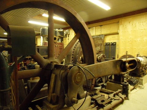 There's another, unheated, hall for stationary engines. The plan is to
add line shafting to the ceiling eventually and power it from this engine.
The flywheel on this
engine is 13 feet in diameter. It's a 1905 150 horsepower engine that drove a furniture factory
for Krug brothers furniture all the way until 1988, when they went out of business.
Before electrification, if you built a factory, you needed to have a big steam engine to power everything. So it was natural that factories had smoke stacks and steam whistles in those days.
One of these engines would have powered overhead line shafting for a factory. The individual machines would then be connected to pulleys on the line shafts via flat belts.
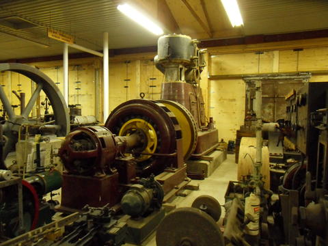 A more modern steam engine and generator from the 1920s It's a 600 hp engine driving a 450 kVA
60 Hz generator. It was made for the Krowler furniture factory in Stratford, Ontario.
The price of electric motors dropped immensely after the First World War. With cheaper electric motors, it made more sense to generate electricity, and use that to power electric motors attached to the individual machines. The power grid was still not powerful enough to run a factory from, so factories had their own generators.
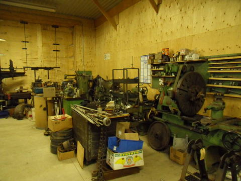 There's also a lot of heavy equipment - various gigantic metal
lathes for servicing some of these engines.
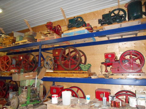 And some old internal combustion engines. Wayne referred to these as "infernal" combustion engines.
They belong to Richard Mosher, chief engineer of the museum.
Richard also collects old woodworking machines
More pages about the steam museum:
Old woodworking equipment at the steam museum
Shingle mills at the steam museum
You can contact Wayne Fisher of the steam museum by phone at:
519-740-7185 or via email at:
![]()
Related pages:
 Sash & Door factory at
 Asam brothers steam powered sawmill