 Hello Matthias
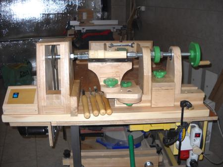
Winter is in full here so outside DIY projects are not possible. So I decided to build another machine for woodworking -- a lathe, with a copier attachment.
I made the whole structure from scraps of beech, ash and plywood. I kept expenses to a minimum and made it from parts that I already had.
The 450 watt 2800 RPM electric motor, 230 volts, comes from a tile saw that I have not used for several years. I bought it during the construction of my house eight years ago. Since then it lay idle on the shelf.
The bolts, nuts, washers, bearings, switch, socket, and pieces of wire are from inventories from earlier purchases. The only new purchase was the drive pulley.
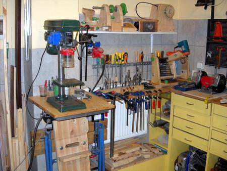 Due to the limited space in my workshop, which is also a garage, the lathe
is modular, easy to disassemble and store. I timed dismantling the lathe
and putting it on the shelf -- it took about 10 minutes.
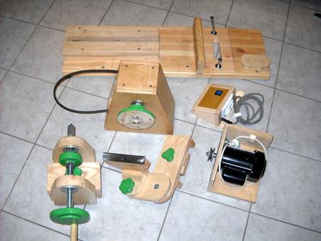 The lathe consists of six modules:
- Base and bed,
- Drive,
- Power module,
- Head stock,
- Tailstock,
- Tool rest
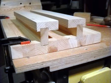 The base for the lathe bed is made of pine strips glued to make a block 95x30x3 cm.
The lathe bed is made from ash, forming two asymmetrical T shapes, 5 cm wide,
and glued into grooves cut into the base, as seen in the picture.
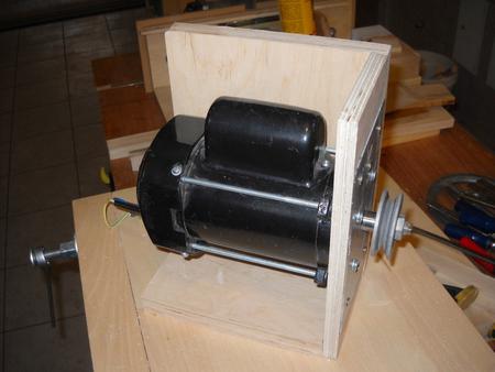
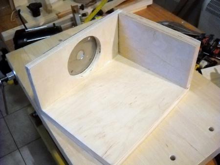
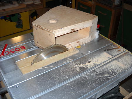
The flange-mounted motor is bolted to the box cover. The pulley on the motor is mounted where the tile saw blade was originally. The motor box is suspended and hinged from the base. This allows gravity belt tensioning and makes it very easy to disconnect the drive from the base unit. I may use the motor module to drive my next machine -- a drum sander, which I plan to build soon.
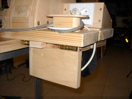 The power module is a small box containing a key switch,
and dual power socket. I may add electronic speed control.
The module is fed with 230 V. One socket is for the motor, the other
for powering a lamp or router for my copy attachment.
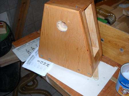
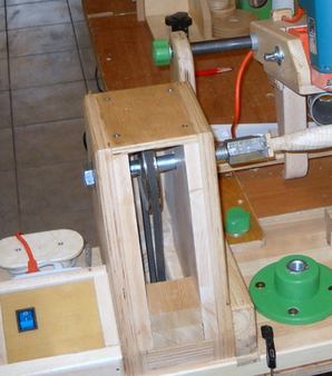
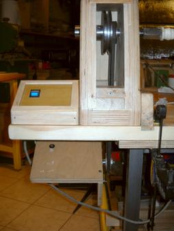 The headstock is 145 x 305 x 290 mm. The housing is
40 mm thick laminated timber and plywood.
The spindle is 220 mm above the base.
The spindle is made from M20 threaded rod, 200 mm long, ball bearings on
either end.
The spindle pulley is 120 mm diameter, and tge motor pulley is 60 mm,
so the spindle speed is 1400 RPM. Later a second pulley was added to
allow runningg the lathe at 2800 RPM (second image at left)
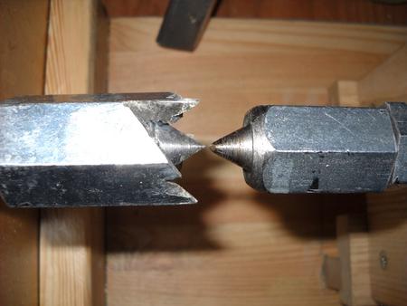
The drive prongs are cut into a barrel nut attached to the spindle.
The face plate is 135 mm diameter.
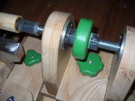
The tailstock is 180 x 215 x 160 mm. The frame is glued together from beech and ash planks. The spindle is 170 mm above the bed (220 mm above the base).
A block of wood in the shape of an inverted T is used to lock the tailstock to the bed.
The tailstock spindle is made from a 350 mm long M20 threaded rod. Turning the crank at the end moves it side to side.
Once in position against the workpiece, the position is locked by tightening the green knob to the left arm of the tailstock.
A M20 coupler nut forms part of the center for the spindle.
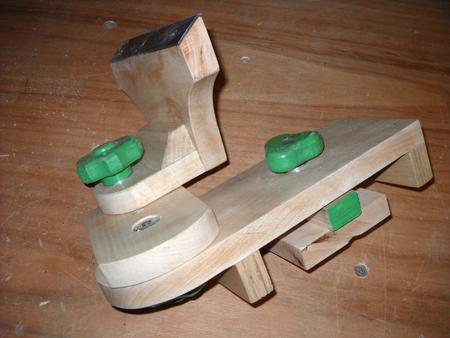 The tool rest is an articulated wooden arm. It attaches to
the bed like the tailstock. The joints
have locking knobs on the screws. The top
of the tool rest is covered with a steel plate.
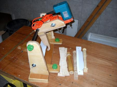 This attachment allows repetitive items such furniture feet, stair balusters,
chisel handles to be made from a template.
It consists of a base, and a slider with two arms that rides on the 3/4" pipe. The copier attachment is attached to the base of the lathe.
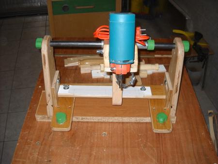 The lower arm of the slider has a 5 mm diameter follower
pin, which follows the template, and the upper arm mounts the router.
Both arms of the slider are the same length and at a 90 degree angle to each other. A piece of pipe, where the arms join, acts as a sleeve to allow it to slide on the 3/4" pipe.
The router has a 43 mm diameter mount near the collet, which is mounted in a handle that is meant for use on a drill. The handle is mounted in a slot in the slider arm.
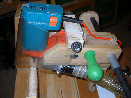 You have to be careful. I used a face mask on the router.
The copier is used as follows: Raise the cutter above the
material, run the lathe, then slowly lower the router.
It can only remove 2-3 mm at a time.
Router specs:
Power: 400 W
Voltage: 230 V
Speed: 26,000 RPM
Router collet: 6 mm
Note:
Instead of a router, a plain cutting tool could be used.
This is my first attempt at a copy lathe. I am still experimenting.
I will probably try mounting a fixed cutter on it also.
Ryszard Grenda
Ryszard later sent me some pictures of the copy lathe using
a fixed chisel (see below).
Ryszard adds:
The knife blade angle is very important!
A video, showing how the lathe and copy carver are assembled:
A video showing use of the copy lathe attachment:
More of Ryszard's projects: