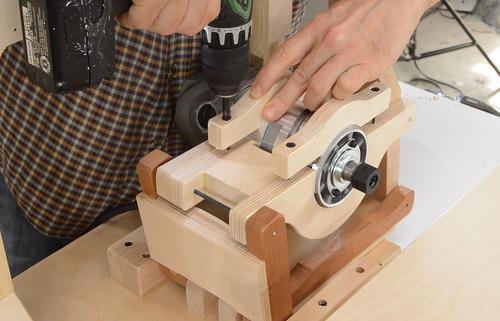
 At this point, the pantorouter was far from done, but I was keen on trying it out
at the earliest opportunity.
 At this point, the pantorouter was far from done, but I was keen on trying it out
at the earliest opportunity.
I made some brackets to clamp the router into the mount on the pantograph.
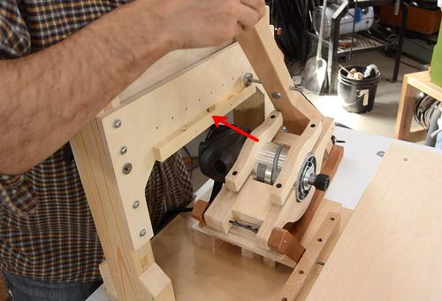 I added a horizontal rail to the bottom of the template holder to help me check
that as I moved the follower horizontally, the router's collet also moved horizontally
along the table.
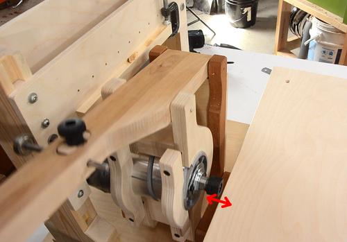 I also moved it left and right as far as I could, checking that the distance between the
router collet and the edge of the table stayed consistent (see red arrows). If it doesn't,
it's likely that the main shaft that the pantograph mounts to is not at a right angle
to the edge of the table.
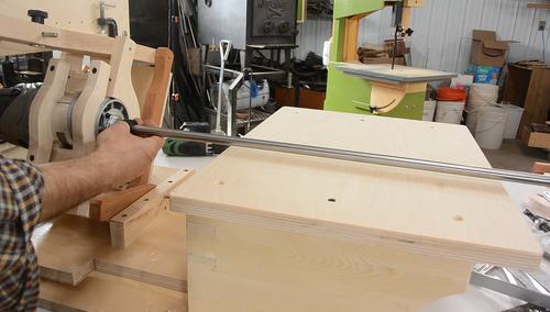 I happened to have some 1/2" shafting material. I put a piece of that into the router
and turned it by hand to make sure it was in there straight.
Moving the router side-to-side horizontally, I checked that the shaft stays level with the table.
If you don't have a 1/2" shaft, use the 1/4" that you need to make the depth stops out of later. A 1/2" dowel might also work if it's straight enough.
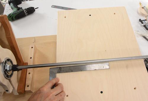 I also checked that the shaft stays perpendicular to the table.
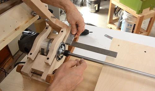 I was surprised how close the alignment was, but there were some minor inaccuracies.
Tweaking the pantograph as a whole is difficult; it's much better to check the individual links for accuracy. Here I'm checking that the router is perpendicular to the front face of the link. This can also be checked just by putting a ruler against the front face of the router, as the front face should be perpendicular to the router.
 I wanted to make a big mortise and tenon template to test it out with.
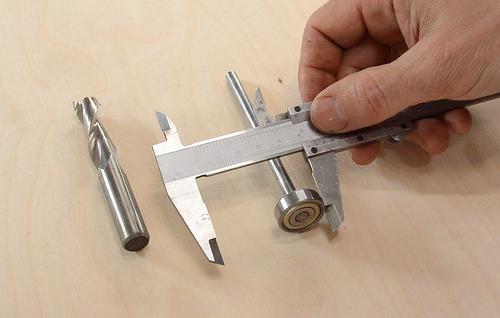
I want to make a tenon 1/2" thick, using a 1/2" router bit. The simple formula that
I like to use is:
(Router diameter + tenon thickness) * 2 = follower bearing diameter + template width.
So that works out to (1/2" + 1/2") * 2, or two inches. With the calliper set to two inches, the space remaining between the calliper and the follower bearing is the template width that I need.
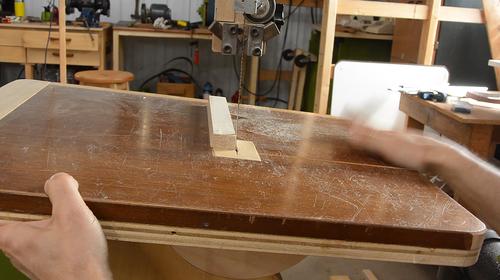
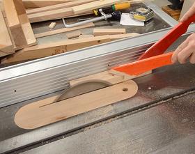
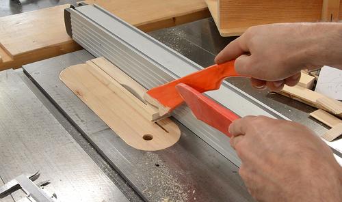 I tilted the saw blade by 8° and cut a strip of wood of the right width with a bevel
on either side. I sized it so that the middle of the bevel has the width that I need.
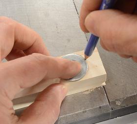 I marked a semicircle on either end of the template using a washer of the right size, then
tilted the bandsaw table by 8° and cut a radius on either end.
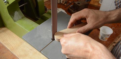 Then finalizing the shape on the strip sander with the table tilted 8°.
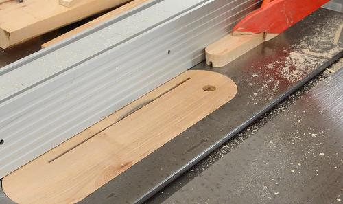
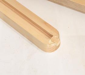 I needed a slot down the middle of the template so I could use that same template
to make the mortises. I cut the slot by making a series of cuts with the table saw.
The slot should be long enough so that the pin can move as far as the center of the semicircles. I glued in a piece of wood at the end, then sanded the ends of the template again to smooth it out.
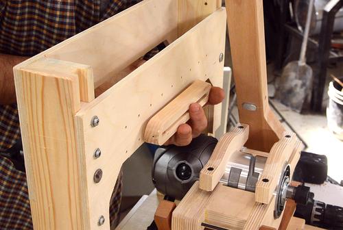
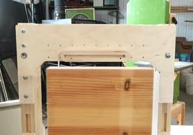 Then I fastened it to the front of the template holder using some wood screws
from the back.
I checked that it was parallel to the table by placing a short board on the table and looked over the edge of this piece to check that the template was parallel.
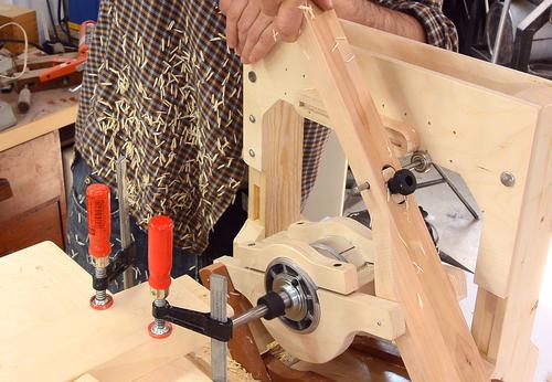 With the template mounted, I cut the first tenon in a scrap of wood.
I just used two bar clamps to clamp it to the edge of the table because I don't have a proper clamping solution yet.
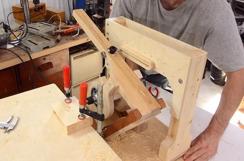 I also cut a mortise. This was not easy to do without a plunge lever to help
push the router into the wood. I just didn't have very good control pushing
it by hand. I need to make a plunge lever, but I didn't want to wait any
longer to test it out.
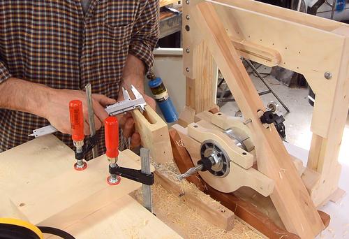 Fitting them together, the tenon was way loose. Perhaps my
router bit was cutting much larger than it should?
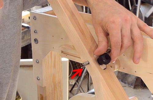 After puzzling over this for some time, I realized my follower bearing wasn't
clamped rigidly enough in the operating lever. The clamp needed some adjustment.
Part of the problem was that I originally drilled the hole slightly crooked, and expanded the hole a bit to allow it to be in straight. But this added wiggle room. I figured my clamp would prevent it from wiggling, but that was not the case.
I stuck a small nail in next to the shaft to keep it from wiggling for the time being (see arrow in red).
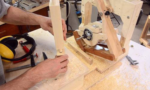 Re-cutting the mortise and tenon joints. I got a proper fit this time.
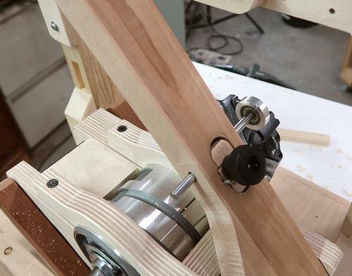 At this point I decided that my clever follower clamp design really wasn't very
clever. It was difficult to make and less effective than the simple block that
clamps the follower on my pantorouter XL.
So I re-built the operating lever link to make a new follower clamp for it.
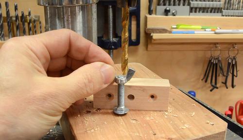 A screw and wing nut go through the block to clamp it together.
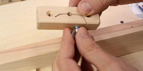 A slot is cut through the block with the bandsaw to allow the block to flex and
clamp onto the follower bearing's shaft.
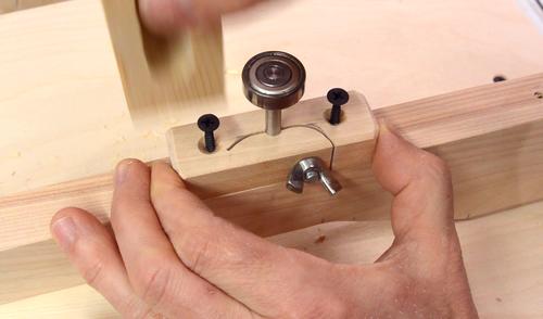 This block screws onto the operating lever. Here I'm tapping the screws with
a block of wood to mark where the pilot holes need to go, then I drilled pilot
holes and then screwed it on.
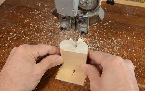 I also made a handle for the operating lever. I started by cutting out a round
piece of wood on the bandsaw (the grain is oriented vertically in this piece
of wood).
You could also use a piece of 1 1/4" dowel for this, or even make the handle square.
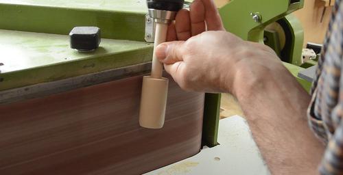
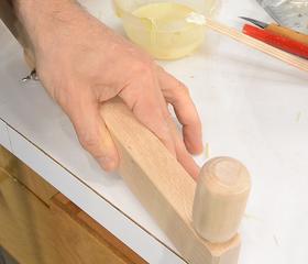 I glued a dowel into the handle, then spun it against the running belt sander
with a drill to smooth and sculpt the handle, then glued it into the operating
lever.
The handle doesn't spin. I figure this helps to prevent the handle from accidentally slipping out of your hands.
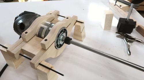
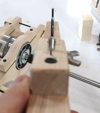 I checked that the pins and follower on the operating handle are in line and the
right distance.
Since I had to take the pantograph apart again anyway, it was time to check the alignment of the router in the link (which I really should have checked earlier). I made five blocks of equal height, then used those to support the router mount link by the pins and checked that the center of the router was at the same height as the center of the shafts of the link. I also checked that the distance between the router shaft and pin on either side was the same, and that the router was perpendicular to the mount.
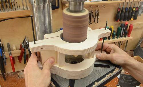 I found the front of the router was off to the side by about 0.2 mm, so I used
a spindle sander drum in my drill press to sand out the mount on one side slightly
and glued a shim on the other side.
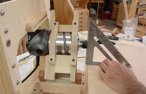 With the pantograph back together, checking it some more. I realized the router
collet moves away from the table when the router is lifted up.
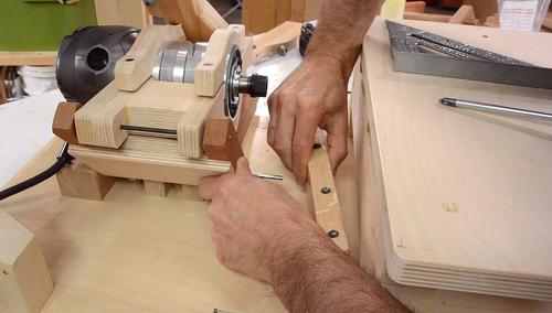
 I realized this was because the front mount of the main shaft is a tiny bit higher
than the back mount. So I removed that mount and cut a tiny bit off the bottom
edge to bring the mount lower. I added some shims under the back mount.
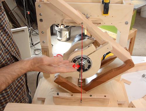 My initial mortise and tenon joints were also at a slight slant. A slant results if
the router is not exactly in line between the follower pin and the main pivot pin
(see line and arrows in red).
Imagine the router was 1 mm to the left of this line. With a tenon that is 3" (75 mm) wide, this will result in both the mortise and the tenon being about 0.6 mm higher on one side than the other. Worse yet, as the mortise and tenon mate, and the mortise is at the same angle, those add up instead of cancelling, resulting in a rather noticeable 1.2 mm difference across the joint.
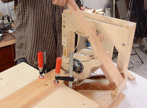
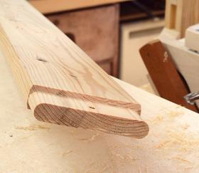 But with all the tweaking done, when I re-cut mortise and tenon joints, there wasn't
any noticeable slant in the resulting joint.
Next: Plunge lever and depth stops