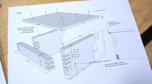
 I'll start with the table on the front. The design for this is almost
the same as in my
previous pantorouter.
I prepared by gluing some pieces of wood together to get the full height
needed for the table supports.
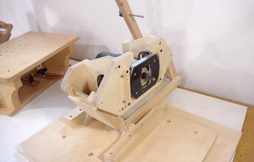 Having built the pantograph and
sliding base, I need
something to hold the stock in front of the router and
something to hold a template behind the pantograph.

 I'll start with the table on the front. The design for this is almost
the same as in my
previous pantorouter.
I prepared by gluing some pieces of wood together to get the full height
needed for the table supports.
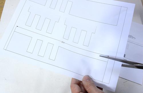
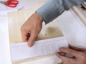 Instead of using a 1:1 printout of the whole sides, I made separate
1:1 printouts of just the joints for this table (I'll include those
in the plans). I paste these on the joined edges of the table pieces.
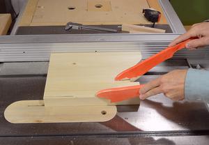
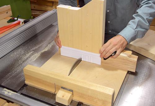 With the template glued on, I line it up one edge of one of the slots
with the saw blade, on my table saw sled, then clamp
a block of wood to the sled as a side stop, and make the first cut.
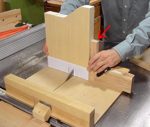
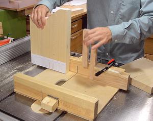 The slots and fingers are 13 mm wide, so I made two 26 mm wide blocks.
Inserting one of these between the stop block and the work piece allows
me to make the next cut without having to line things up by eye.
Then another block inserted, and the next cut made.
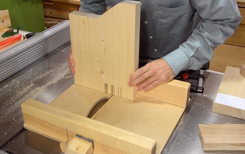 I use the same method to make a cut on the other side of each slot, then
hog out the material for the rest of the slot by making a series of cuts
with the saw blade, just positioning the workpiece freehand for each
cut.
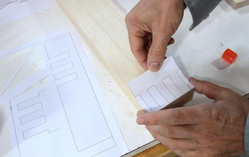 Next the fingers on the part that links the two pieces together.
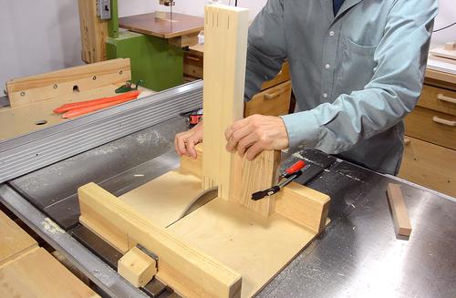 Same procedure with the spacers.
Having cut the joints, the fingers were too wide to fit, so I positioned the stop block to shave half a millimeter off each finger, again using the spacers to position for each finger.
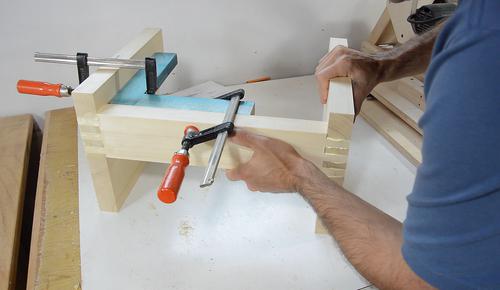 Gluing it together. No need to clamp these joints, but I used one of my
clamping squares
to make sure the first joint stayed square as I glued the second one.
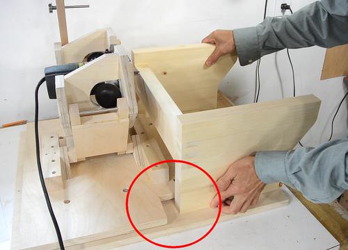 With my other pantorouter, I often found shavings accumulating in the
corner circled here.
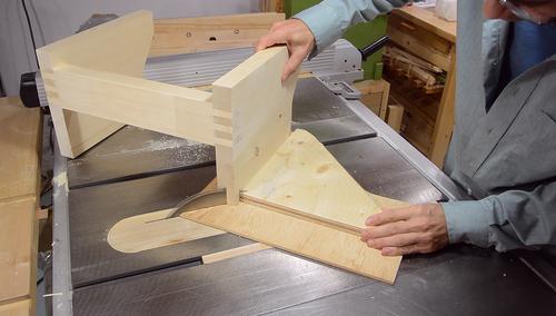
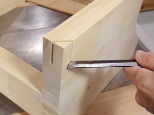 So I cut out a notch in the corners of the table support, just with
a 45-degree cut on the table saw, then chip out the rest with a chisel.
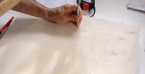 The table top has a grid of holes in it for mounting the clamp onto.
I could have used a 1:1 template to mark these, but drawing the grid was
easy enough and saved me the trouble of peeling the paper off afterwards.
I'm using an awl, tapped with a hammer, to put a divot on each grid intersection...
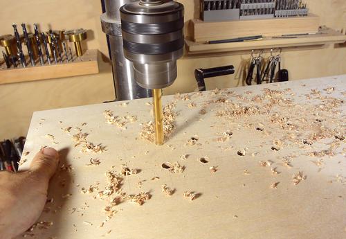 ... then using a 25/64" (just slightly bigger than 3/8") drill to drill out the holes.
After that, I use a countersink bit to chamfer the edges of the holes.
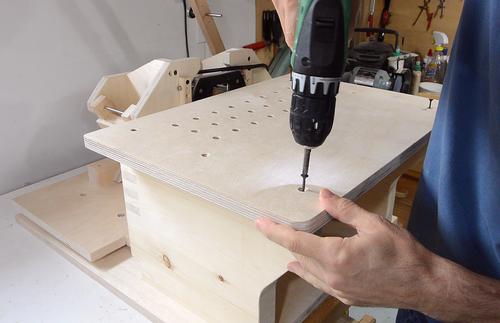 And attaching the table top. I'm only using four short screws for
the time being because I'll take it all apart again for varnishing later.
The table itself is screwed onto the base from the bottom, though I took no photos of that.
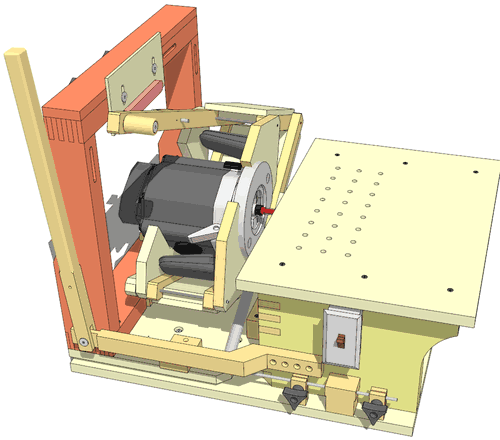 Next comes the template holder (highlighted in orange) which sits behind
the pantograph.
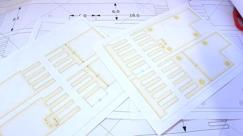
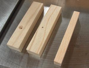 I initially designed these joints to be cut with my
screw advance box joint jig,
but I wanted this machine to be easier to build for people who don't have
my fancy jigs. So I had the idea of using the same method that I used to cut the
joints for the table. But to make it easier, I changed the fingers to be 8 mm
wide from 6 mm.
I made some spacer blocks, one 16 mm wide (one finger + one space) and two 32 mm wide (two fingers and two spaces).
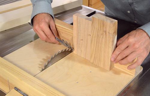 With the three spacers I can make any multiple of 16 mm. This way I
get less cumulative error than using five equal blocks.
I knew the first slot leaves an 8 mm finger, so with the spacers in place, I used my calipers to position the stop block so that there were 8 mm between the last block and the blade. I didn't bother pasting the templates onto the wood.
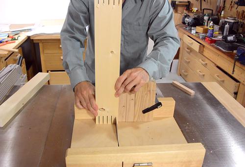
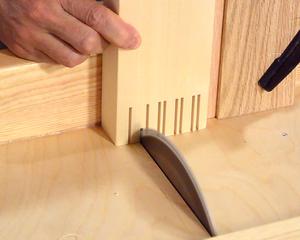 Cutting the fingers. First cutting the horizontal pieces, cutting the
slots in each end. Then moving the block so that the next cut is the
other side of each 8 mm wide slot, then placing it freehand to make
two more cuts in between to hog out the 8 mm widths.
Except I made a mistake. When I cut the joints on the verticals pieces, after having cut the horizontal ones, I didn't offset them correctly. I should have started with the first 8 mm from the edge cut away. So I had to make these pieces a second time.
The vertical pieces are narrower at the top, but I hadn't cut this away initially.
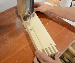 I cut the straight part of this cut on the table saw, then cut the angled
part of the cut on the bandsaw.
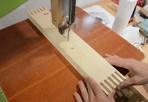 The bottom horizontal piece also has a big square cut-out to make room
for the rear mounting block for the pantograph.
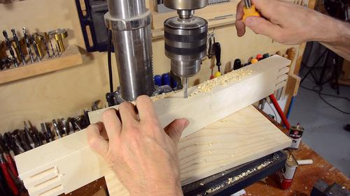 I also need to cut some slots into the template holder.
I'd normally cut these with my
slot mortiser,
but again, I have to make sure the machine is buildable without all my
jigs. So I figured I should cut this out with a plunge router.
To make the work a bit easier, I hogged out some of the material by drilling a series of 1/4" holes where the slots need to go.
It is possible to hog out a slot strictly with a drill press, but it's best done with a short router bit or endmill. With a drill, it always ends up messy looking.
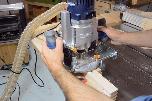
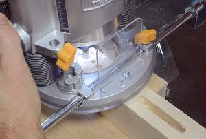 I then remove the rest of the material with a plunge router. The router
has an attached fence to help me guide it.
I'm using a 3/8" straight router bit. I have to route from both sides to make it all the way through.
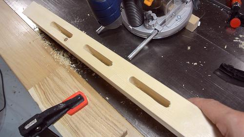 Slots cut. The alignment wasn't perfect. I could have cut the slots
faster and in less time using my slot mortiser.
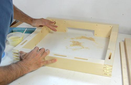
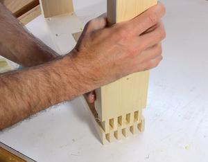 Finally, I drill the mounting holes in the bottom horizontal (I didn't
take any photos of that), and then glue the frame together.
After putting it together, I leave the frame lying flat on the table, so that I don't accidentally introduce any twist with the clamps.
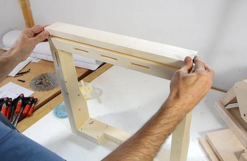 I also glue a strip of wood to the top, which gives me more room for clamping
templates on, especially when attaching templates with just clamps.
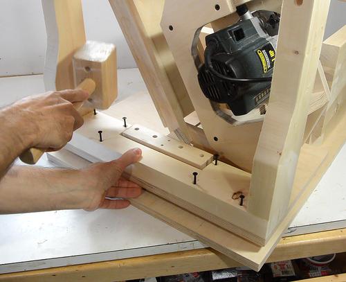 Placing screws in the mounting holes, and tapping them with a hammer to mark
the pilot hole locations.
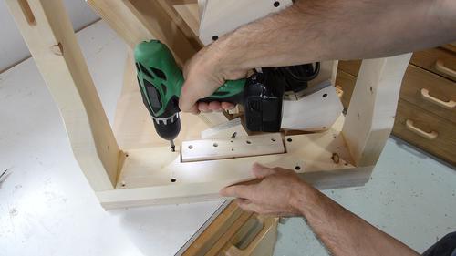 After drilling pilot holes, I screw on the template holder. Just four screws
for now, because I'll have to take it all apart again later for varnishing.
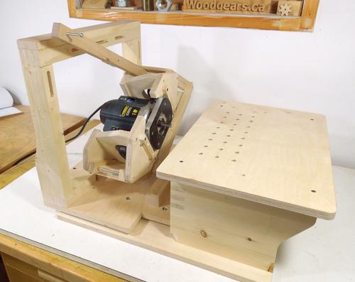 The pantorouter so far. I'm keen to try it out, and I really need
something to clamp the
followers to do a good job of that, so that's next
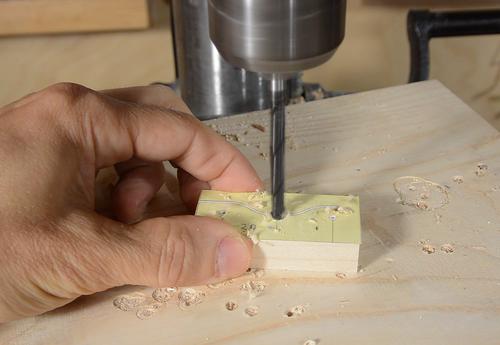
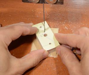 The follower clamp is a small block of wood that clamps to the operating lever.
I'm using a paper template for the shape of it. It needs to be very precisely
made, to make sure the follower bearing doesn't mount crooked on the operating
lever.
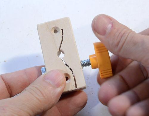
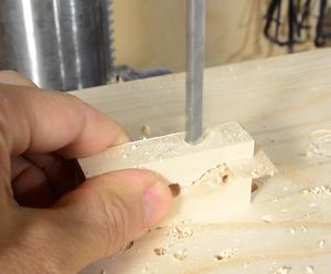 A hole goes through the side to allow a bolt and knob to squeeze the block
together, clamping the 1/4" (6 mm) shaft for the follower bearing in place.
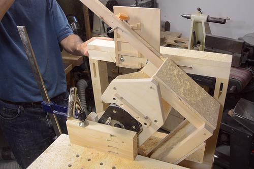 Testing it out, using a multiple-mortise template. I first made this template
for some joints for a mirror stand.
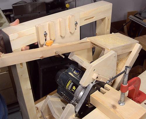
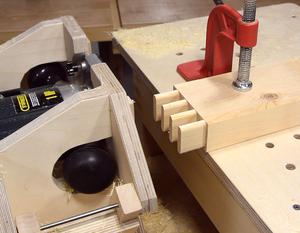 And carving the multiple tenon joint to go into the multiple mortise joint.
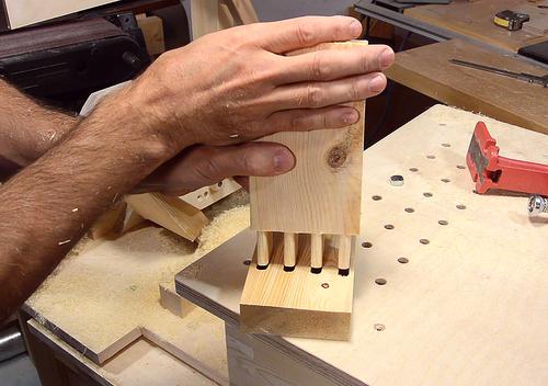 The fit was less than perfect. I must have some minor geometry error in the
pantograph. I will have to check that later.
Next: Plunge lever and plunge stops
I also had a timelapse camera running while I was shooting below.
I added narration to the timelapse. Might be intersteting to you, but maybe not.