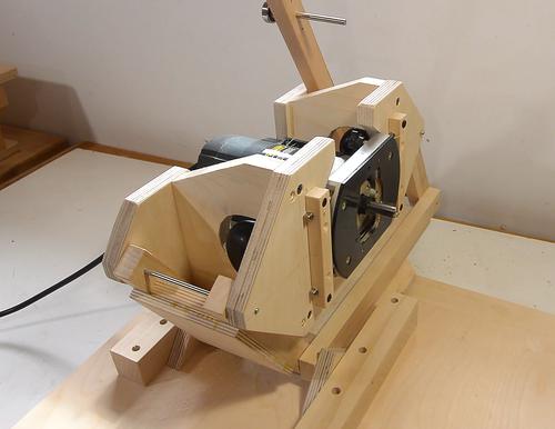
 Having built the pantograph mechanism
for my new pantorouter XL,
I next need some linear glides to allow the base that the pantograph
mounts on to move forwards and back (parallel to the router's axis)
 Having built the pantograph mechanism
for my new pantorouter XL,
I next need some linear glides to allow the base that the pantograph
mounts on to move forwards and back (parallel to the router's axis)
But this pantorouter is designed to take a plunge router, so why not just use the router's own plunge mechanism for the plunge action? The problem with the plunge mechanism on the router itself is that it's difficult to activate and it doesn't have enough plunge range. With the pantorouter, when cutting tenons, those are typically cut with the stock overhanging the end of the table (shown at left). But when cutting mortises, the stock is mounted on the table, so the router needs to come further forward to plunge above the table. The router's own plunge mechanism doesn't have enough travel to allow for both.
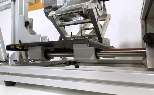 A good solution for the plunge action is to use polished steel rods
and linear bearings, as is done with the
all metal pantorouter.
But these are expensive, and you can't just walk into
your local hardware store and buy them.
Another downside of linear glides is that they add a lot of height.
 I'm going to use drawer glides. However, full extension slides, such
as the one shown at left, with two glides telescoping, tend to have too
much play in them and are unsuitable. Unfortunately, most full extension
drawer slides are of this variety, so you have to look around to find a
slide that is suitable.
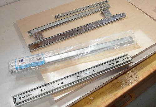 Suitable for this type of work are glides with just one set of balls.
These include good quality keyboard drawer slides, older style two-tier
full extension drawer slides, and center drawer glides. The slide
at the bottom of the photo is a full extension slide that is not
suitable.
The center drawer slides (one still in the package at left) are a good find, in that they are very close to what I need. I found these at Lowes. And Lowes also sells the springs you will need for a later part of the build, so it's worth a visit (Home Depot sells neither part).
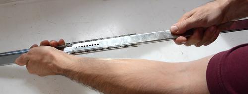 The center drawer slides have a mounting piece that is easy to pull
off one end. And the slides themselves can also be separated by
pulling hard on them.
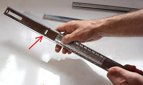
 With the inside part pulled out, we have what I like to call the "ball
cage" which holds the bearing balls in place. Metal tabs on either end of
the outside track keep the ball cage from moving too far.
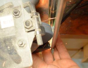
For these modifications, I need remove one of the tabs (arrow in red). I ground it off with a bench grinder. I could have flattened it with a hammer as well, but that risks bending the track.
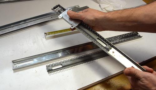 I only need 12 cm range of motion. To beef up the linear
glide, I'm going to add another ball cage. I'm taking these off some
other ball glides that I pulled out of the garbage. Fortunately, most of
the good quality ball glides have the same profile and ball size.
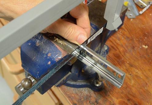 Cutting the outside track to length. I want it to be about
43 cm in length.
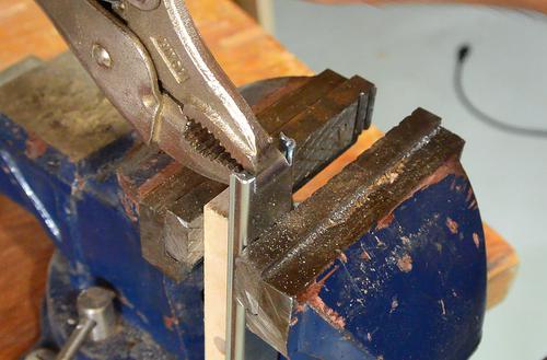
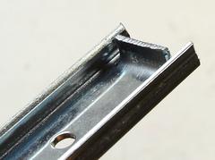 Having cut the inside track to the right length, I cut some slots in the
end of it and bent a tab on it. This hook catches the ball cages
and will help keep them in place.
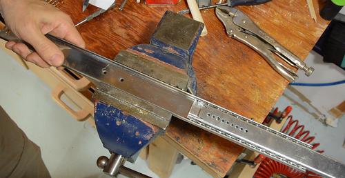 Last time I
adapted some linear glides, the glides I used had a small amount of
play in them. I eliminated that by squeezing the track together a bit in
a vise - being careful to not over-squeeze it (with lots of squeezing
and testing), and always making sure the balls are not where the track
is being squeezed. You may have to do this with yours. The tracks I
bought from Lowes were tight to begin with, so this wasn't necessary.
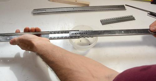 Next I need to drill mounting holes. That is done with the tracks
completely disassembled. With one of the limit stops ground off earlier,
I can pull the glide completely apart, catching all the ball-bearing
balls in a container as they come out.
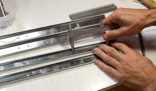
 I'm mostly using existing holes, but a few new holes need to be drilled
as well. I'm using calipers to scratch where the new holes go,
measuring from the existing holes. This way, I'm able to establish the
new hole locations very consistently.
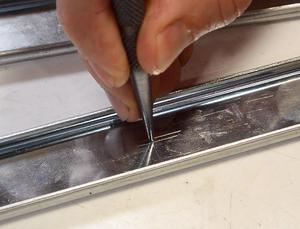
I then use a center punch to put a divot where the holes need to go.
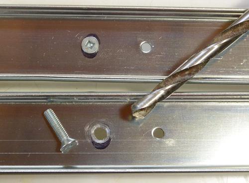 The divot helps to guide the drill in the right place. Without a divot
in the metal, the spinning drill would wander a bit before starting to drill.
It's really nearly impossible to start an accurate hole without a divot.
I drilled a small (1/8" or 3 mm) pilot hole, then a larger hole for the screws, and then used the tip of a larger drill to chamfer the edges of the holes for mounting some countersink screws.
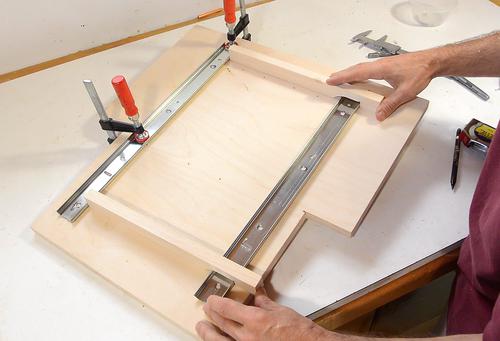
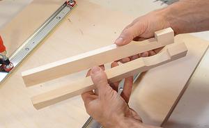 Next I need to mount the wider outside tracks to the bottom of the
"sled" that the pantograph mounts on. These need to be exactly parallel.
I made two spacers on the table saw. These are designed to catch the same edge of both slides, so that the center to center spacing will be the same regardless of the slide width. I cut these from one piece of wood, then cut that down the middle to make sure I had two spacers of exactly the same length.
I then use these to position the glides just right...
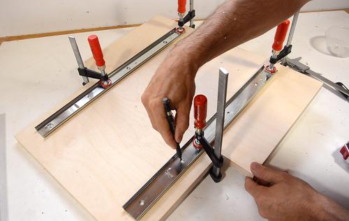 ...then mark where the holes need to go
and use an awl to put a divot at the center of each mark.
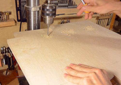
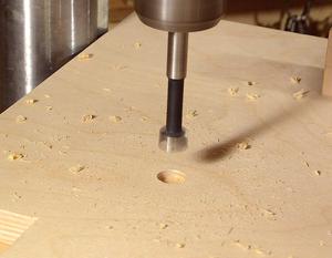 I drill holes slightly larger than the screws to leave
a bit of slack for the screws so that I can make final adjustments
later.
I also drill a hole from the opposite side, deep enough for a nut and washer to fit below the surface.
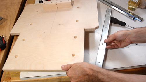
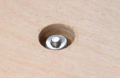 Screwing the rails on. Getting the nuts and washers on is always a
fiddly task. I use a nut-driver to tighten the nut in the hole.
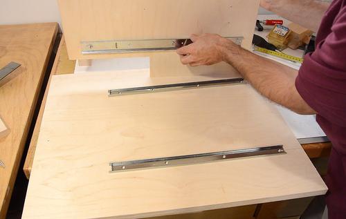 Next I need to mount the inside tracks on the base of the machine.
These are slightly shorter. The idea is, as the top slides back and
forth, the track below will always be covered by the sled above it.
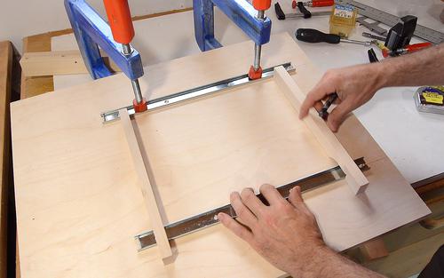 I'm using the same spacers to lay these out as I did for the sliding
part. Because they both reference the same edge on both parts, they
still produce the same spacing for the narrower tracks.
I then screw on the tracks the same way as the ones in the sled are screwed on.
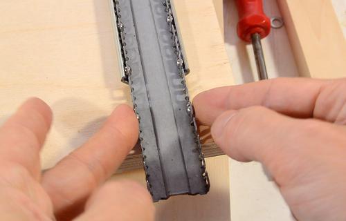 Now putting the ball cages and balls back in. Getting the balls in is
also fiddly. I cleaned the tracks, ball cages
and balls of any grease, seeing that all my other work may have
contaminated the grease.
I cleaned out all the grease and am not re-greasing for the time being because this is not the final assembly.
It works reasonably well to hold a ball from either side with each hand as and push the ball cage in by one ball increment at a time. I'm only placing a ball in every third position for now.
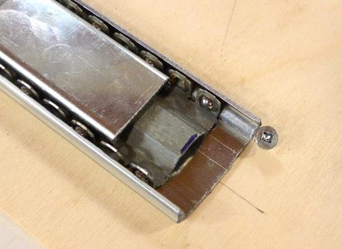
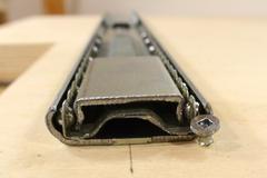 In the original slides, tabs prevented the ball cages from sliding out of
the outside track. But with one of the tabs ground off, I added a screw
at the end of the track to keep the ball cage from coming out. I put
that screw towards the side because it was the only safe place to be
clear of the middle track, with its tab that also has to move past
the end of the track.
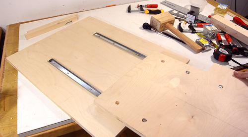 I'm mating the tracks together. The tracks on the base are parallel
and firmly screwed down, while the tracks on the sled have the screws
left loose.
Once the two parts are slid together, the slack in the mount should now allow the tracks to mate precisely. I can now tighten the screws in the sled to make sure everything is locked in place.
An advantage of using ball glides is that they slide easily, even under pressure. That way, I can push the plunge slide forward and back from the side without risk of jamming (racking).
I also had a timelapse camera running while working on these:
Timelapse video of making the glides
Next: Table and template holder