Building a lathe stand
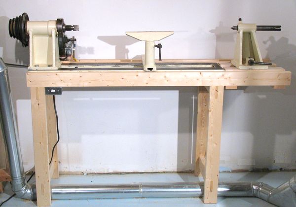
Many years ago, I bought an old home made lathe at a yard sale. The lathe
had been built by somebody many years ago, by welding together half inch thick steel
plates and angle irons, and weighed a lot more than I did.
In my old workshop I just had the lathe standing
on top of a workbench that was actually an old metal desk. But for my new
basement workshop,
I didn't want to dedicate a workbench to it, so it was time to build a
proper lathe stand for it.
 Although I decided on construction very similar to my
workbench, I decided to use mortise and
tenon joints for this one rather than dowels this time. The thing being,
with good setup for making mortises
and tenons, it doesn't take more time, and its easier to get it accurate.
There's just something very satisfying about cutting mortises. Especially
for through mortises, when you see the bit break through the piece of wood.
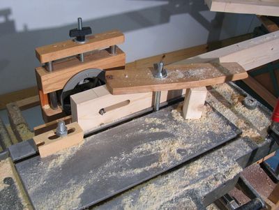
I cut these tenons to be 5/8" wide, using an endmill in the router.
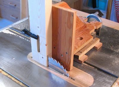 The tenons I cut with my home made tenoning jig. The picture at left shows
cutting the tenons at the top end of the legs. These are fairly deep - as deep
as I could cut with my mortising machine - 6 cm.
The slot you see in the work piece at left is for the brace that goes between the legs.
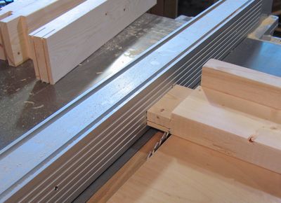 Cutting the shoulders of the tenons. Its much easier to just cut these separately
afterwards. I suppose I could cut away the tenons with a dado blade, which would make
this step entirely unnecessary, but this method is quick and produces a cleaner cut on
the shoulder.
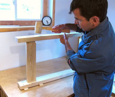 Test fitting the leg frames together. I like it if it takes a bit of force to get the whole thing
together. The rubber mallet is also very handy when doing the final gluing - if it binds
at all during assembly, there's only one thing to do - hit it with a hammer to make it go,
and do it quickly before the glue sets. In tight joints, the glue sets relatively fast.
And if it won't budge when you hit it, hit it harder!
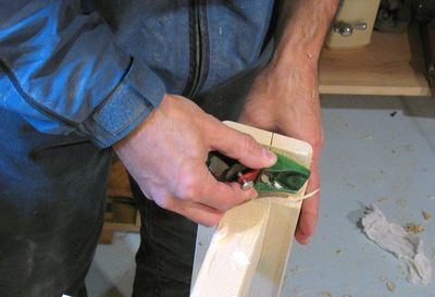 I made the tenons just a little too thick though, so I planed them down just a tiny little
bit with a hand plane before final assembly.
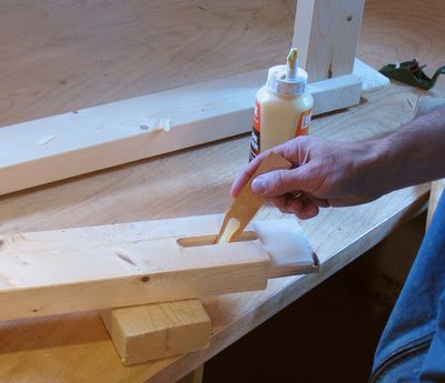 On gluing it together, I always make sure I have all the surfaces covered with glue. With
a tight joint, there's already risk that the glue gets scraped out of the joint when
assembling it. But I figure that is less likely if all surfaces already start out with
glue on them. I also cut a slight chamfer on the ends of the tenons, which hopefully allows
the glue to get scraped out less.
I use a wooden split to coat the insides of the mortises with glue.
 And this is what the frame of the lathe stand looked like, before I attached
anything to it. The legs are mortised into the bottom of the horizontals,
and the cross braces mortised into the legs. 12 mortise and tenon joints in all.
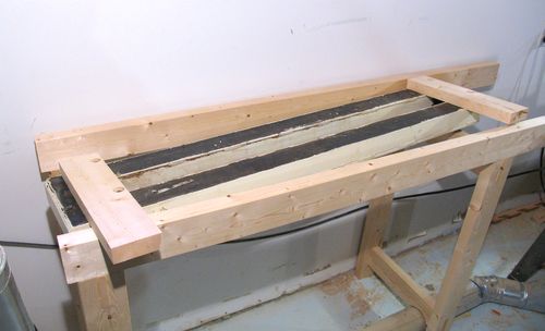 I bolted some pieces of wood to the bottom of the very heavy lathe bed, which I then
flipped over, and screwed these pieces of wood into the top crossbraces of the legs.
This brought the top of the lathe bed about flush with the rails that
go parallel to the bed (side to side).
The advantage of putting the frame rails next to the bed is that its easier to
reach under the lathe to tighten the screw for the tool rest and tailstock,
and leaves more vertical room under the lathe for storage.
Note also that the stand is a lot wider (deeper) than the bed. It needed more width
to give it stability anyway, and that way, there'd be room to mount the motor behind
the lathe, and for drawers underneath later.
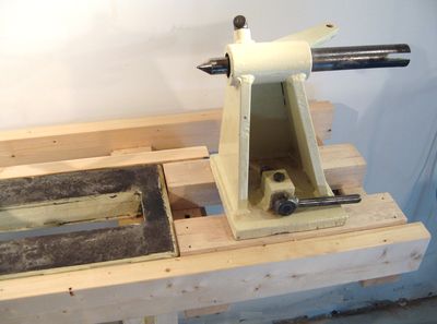 I made the stand extend beyond the bed on the tailstock end, so that I could mount
my wooden lathe bed extension there. I had originally made that lathe extension
for turning the bed posts for
this bed frame
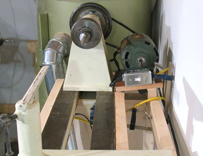 And finally, mounting the motor.
The lathe had come with this gigantic 1.5 hp, 3500 RPM 220 volt motor - way overkill
for a lathe. So I used an old 1/2 HP motor I had picked up from the curb.
The motor turned out to need minor repairs - it had seized bearings, and the starter
capacitor needed replacing. I used a starter capacitor from a different motor,
which I mounted underneath the motor.
The switch in front of the motor is not the power switch - its a 4-way light switch,
which I use to reverse the polarity of the starter winding, so that the lathe can
easily be run in either direction. The main power switch is on the front of
the lathe.
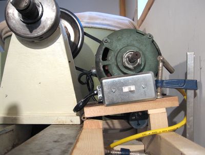 The motor is mounted on a piece of plywood, which is hinged against a rail just
behind the lathe. This rail can be slid along the bed, to allow different parts
of the two stepped pulleys to be aligned with each other.
The hinge allows the motor to tip towards the lathe's headstock pulley. I figured
I'd rely on gravity to tighten the belt, but it turns out that at some speeds,
the motor jumps around a bit and causes a lot of vibration. So I use a small F-clamp
and a block under the motor mount to fix the motor in place for any particular
speed.
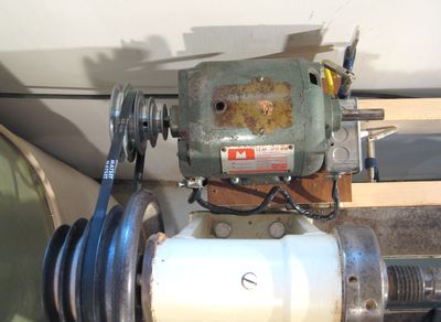 And seen from the top. With me being able to move the motor along its axis, and nearer
and further from the headstock pulley, I can put the belt on any combination of pulleys,
so that I can set the speed from around 600 to 2000 RPM with many steps in between.
I don't use my lathe very much. Mostly it has
other things stacked on it. Some of the projects that I used the lateh for
include turning some bed posts for a bed,
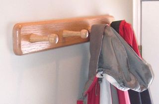
coat hooks,
marbles machine parts,
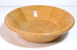
and a segmented bowl.
 Although I decided on construction very similar to my
workbench, I decided to use mortise and
tenon joints for this one rather than dowels this time. The thing being,
with good setup for making mortises
and tenons, it doesn't take more time, and its easier to get it accurate.

 The tenons I cut with my home made tenoning jig. The picture at left shows
cutting the tenons at the top end of the legs. These are fairly deep - as deep
as I could cut with my mortising machine - 6 cm.
 Cutting the shoulders of the tenons. Its much easier to just cut these separately
afterwards. I suppose I could cut away the tenons with a dado blade, which would make
this step entirely unnecessary, but this method is quick and produces a cleaner cut on
the shoulder.
 Test fitting the leg frames together. I like it if it takes a bit of force to get the whole thing
together. The rubber mallet is also very handy when doing the final gluing - if it binds
at all during assembly, there's only one thing to do - hit it with a hammer to make it go,
and do it quickly before the glue sets. In tight joints, the glue sets relatively fast.
And if it won't budge when you hit it, hit it harder!
 I made the tenons just a little too thick though, so I planed them down just a tiny little
bit with a hand plane before final assembly.
 On gluing it together, I always make sure I have all the surfaces covered with glue. With
a tight joint, there's already risk that the glue gets scraped out of the joint when
assembling it. But I figure that is less likely if all surfaces already start out with
glue on them. I also cut a slight chamfer on the ends of the tenons, which hopefully allows
the glue to get scraped out less.
 And this is what the frame of the lathe stand looked like, before I attached
anything to it. The legs are mortised into the bottom of the horizontals,
and the cross braces mortised into the legs. 12 mortise and tenon joints in all.
 I bolted some pieces of wood to the bottom of the very heavy lathe bed, which I then
flipped over, and screwed these pieces of wood into the top crossbraces of the legs.
This brought the top of the lathe bed about flush with the rails that
go parallel to the bed (side to side).
 I made the stand extend beyond the bed on the tailstock end, so that I could mount
my wooden lathe bed extension there. I had originally made that lathe extension
for turning the bed posts for
  And finally, mounting the motor.
 The motor is mounted on a piece of plywood, which is hinged against a rail just
behind the lathe. This rail can be slid along the bed, to allow different parts
of the two stepped pulleys to be aligned with each other.
 And seen from the top. With me being able to move the motor along its axis, and nearer
and further from the headstock pulley, I can put the belt on any combination of pulleys,
so that I can set the speed from around 600 to 2000 RPM with many steps in between.
 Building a lathe from scratch
 Drawers for the lathe stand
 Making bed posts
 Turning a segmented bowl