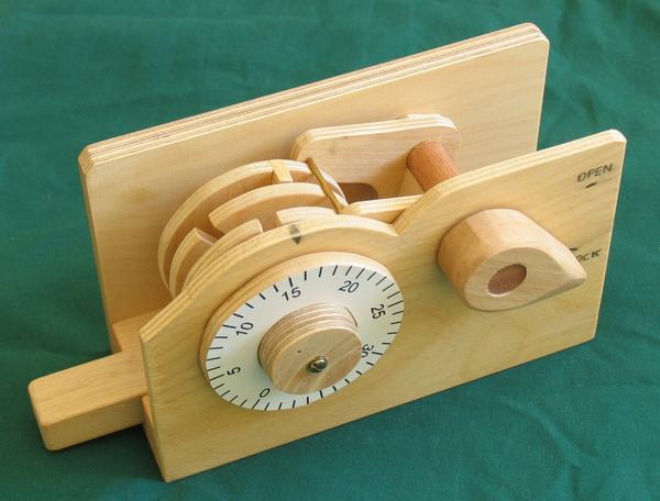
In terms of neat mechanical things to build out of wood, I figured a single dial sequential combination lock would be a neat thing to make. It would be relatively simple, involve movement, and also show people how a combination lock actually works.
I spent some time thinking about it, and the design I came up with was the simplest that would also be visually appealing that I could come up with. Unlike a real lock, my priority was to show how it actually works.
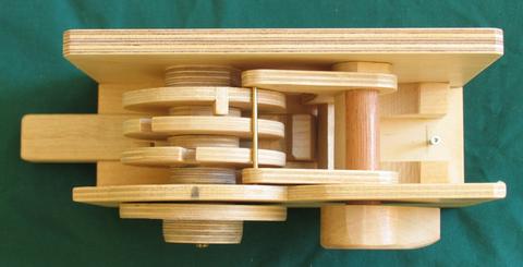 Like most real combination locks such as a Dudley or master Combination locks, the core
of this lock consists of three rotors. Each rotor has a notch in it, and when the three
notches line up, some sort of bar can drop into them, and allowing the lock to be opened.
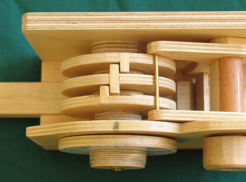 The front most rotor is directly coupled to the dial on the front of the lock.
All the rotors have tabs sticking out the front and back, so that once the front rotor
is turned by one turn, its tab hits the tab on the middle rotor. The middle rotor's tab
in turn sticks out the back, and with another clockwise turn of the dial catches
the tab in the last rotor. So with two turns in the same direction,
the back rotor is also engaged.
To open the lock, one turns the dial to the right until the notch on the rear most rotor is aligned with the bar. The first number of the combination corresponds to the position that the dial needs to be turned to accomplish this.
After the back rotor is lined up, rotation is reversed. By turning counterclockwise one turn, one will catch the middle rotor with the tab pushing it in the opposite direction. As long as one doesn't turn too far, only the front and middle rotors now turn with the dial. The dial is turned far enough to align the middle rotor.
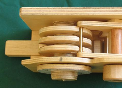 After that, the rotation is again reversed, now turning clockwise again until the
notch in the front most rotor is lined up with the bar. The picture at left shows
all three notches lined up. The lock is ready to open.
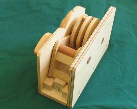 This view shows the bar in the slots. The lock is constructed in such a way that the
bar getting into the slots actually turns the rotors a little bit.
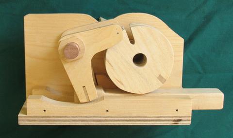 This view with the back panel removed better illustrates how the lock opens.
The L-shaped part on the left turns clock wise to open the lock. This pulls the
bolt (on the bottom) back to the left at the same time.
The notches are not quite lined up in this shot. You can barely see the end of the bar that needs to drop into the notches protruding through the L shaped bracket.
The lock isn't actually functional without the back panel. The shaft that the rotors sit on is part of the back panel, so this shot just has the rotors carefully stacked in place where they would go without their shaft, just to illustrate.
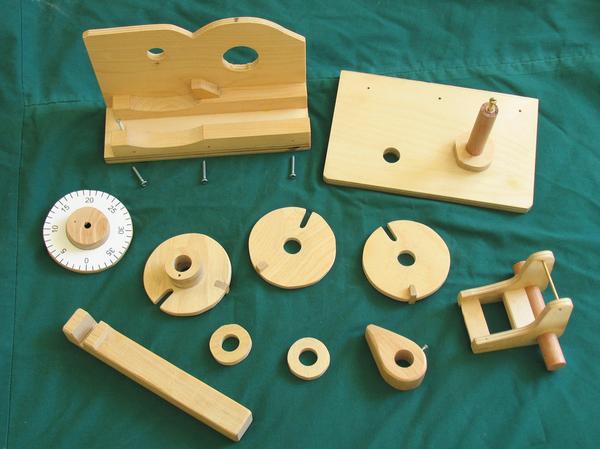 And here's the lock disassembled, showing all of its parts. Really, there is not very
much to it. Note that the shaft that the rotors turn on is glued into the back
piece of the plywood. This shaft itself doesn't turn. The rotors are semi-loose on this shaft.
Ideally, they would turn with a bit of friction so they wouldn't overshoot with momentum
when dialing a combination quickly.
The most complicated part is the part with the bar that drops into the notches, and that part is really only as complicated as it is to make the internal workings easier to see.. On a real lock, the corresponding part would be much simpler and more robust.
Please note that while I sell plans for the combination lock, I do not sell the finished combination lock, and I also don't sell kits for it.
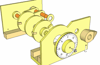
|
You can also Buy detailed plans for this combination lock |
The left-right-left combination lock trick
There's no reason a combination lock has to be opened turning right left right. Really. Any set of rotations that lines up the rotors will do. This video demonstrates opening a lock by turning left-right-left. This involves dialing the lock to a different set of numbers than the regular right-left-right combination.
How to work out the left-right-left combination
Building the combination lock (Build article)
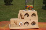 Michael Schultheiss's secure candy dispenser
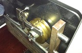 Jason Lucero's metal
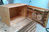 Steve Zhang's Combination lock safe
Back to my Woodworking website