Wooden air engine 1
|
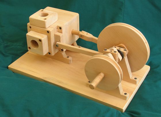
There's something about reciprocating steam engines that is just fascinating. I have even heard it said that every self respecting machinist has at some point built a steam engine.
I was never into machining, and I never had access to a machine shop. But I always enjoyed building reciprocating engines out of Lego. These could be run just by blowing into them, or for more speed, by connecting them to a vacuum cleaner. At some point, when I was still a teenager, I decided to try building a bigger air engine out of wood.
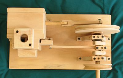 The engine is a double action reciprocating engine, with a square wooden piston. I even made
some pulleys for it so I could try to power things with it. Though really, this engine isn't capable
of developing any torque. It would run pretty fast if connected to a vacuum cleaner though.
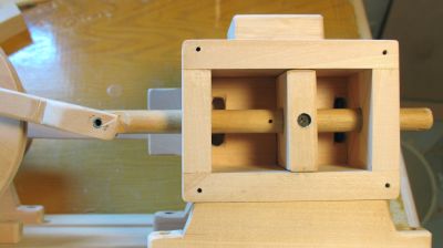 The reason the engine wasn't very powerful was because, in order to make the piston slide very easily,
I ended up having a sizable gap around the piston, which resulted in a fair amount of blow-by.
The engine did run very freely though, so that it could be powered with a stream of air that corresponded
to just 4 cm head of water - very low pressure.
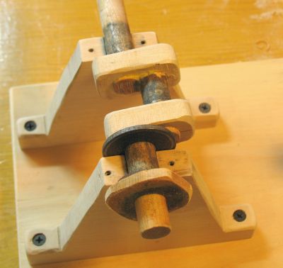 For the main crank, I just put a screw off center in the flywheel. But I still needed a secondary
crank 90 degrees out of phase to activate the valve block with. I was rather happy with how this
crank set turned out.
I started by gluing a short dowel alongside the main dowel for the shaft, along with the blocks. I then cut away most of the shaft itself with a band saw, and whittled what was left round. As it is, a small sliver of the main crankshaft dowel still connects both ends, because the two shafts I used overlapped a little bit.
For the bearings, I just ran hardwood on hardwood, with a little bit of axle grease and oil on it.
This combination worked surprisingly well.
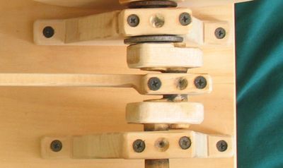 The bearings are all made of two halves, sort of like the old babbitt bearings. I made these by
screwing a block onto the piece of wood, and the, with the block screwed on, drilling through
it with a forstner bit. If I had drilled before I cut the blocks apart, I would have lost
material to the cut.
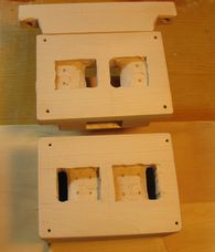
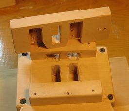 And finally, the valve assembly. The left shot shows the air channels for running the air to
the ends of the piston. The two halves are screwed together facing each other.
The shot at right shows the valve block, above the valve block assembly. The intake air
comes in from the top, and goes through either of the clots in the valve block, while the gap
in the middle of the valve block allows the air from the other side of the piston
to vent outside.
|
More Wooden machines To my Woodworking website. |
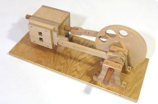 Wooden air engine 2 |
I have since built another air engine and have plans for sale for this engine. |